The short answer
Disconnect the electrode from the system, short E1 and P1 to the electrode, drive one spike about 15 to 20 metres away on P2 and another a further 15 to 20 metres on E2, press TEST and read the display. Move the middle spike a little to check the reading holds steady.
What you need
- A digital earth tester such as the DET-2000
- The testing kit: spikes, wire spools and a hammer
- A tape or measuring wheel
- A way to disconnect the electrode from the installation (a test link or removable connection)
Three-terminal method: earth resistance
- Disconnect the earth electrode from the system it serves, so only the electrode is measured. Where a test link is fitted, open it.
- Short terminals E1 and P1 on the tester with a link or a short lead, and connect them to the electrode with the first wire.
- Drive a spike into the ground in a straight line away from the electrode, about 50 to 70 ft (15 to 21 m) away. Connect it to terminal P2.
- Drive a second spike a further 50 to 70 ft along the same line. Connect it to terminal E2.
- Press the TEST switch and read the resistance on the LCD. Choose the lower range if the reading is small, for the best resolution.
- Check the result. Move the middle (P2) spike a few metres closer and then further out. If the reading barely changes, it is reliable. If it moves a lot, the spikes are too close to the electrode or to each other, so increase the spacing and repeat.
Four-terminal method: soil resistivity
Soil resistivity is used to plan the position and depth of a new electrode system. Bury all four spikes in a straight line with the same distance L between each, between 50 and 70 ft, and connect them to E1, P1, P2 and E2 in order. Press TEST and note the resistance R in ohms. The resistivity is 2πLR, in ohm-centimetres if L is in centimetres, or ohm-metres if L is in metres. Repeat with different spacings to see how resistivity changes with depth.
Reading the result
Compare your reading with the target set by your site rule, standard or utility. Many installations ask for a few ohms, with substations and power stations asking for the lowest values. If the reading is too high, the usual remedies are to add electrodes in parallel, drive them deeper, or treat the soil around the electrode, then test again.
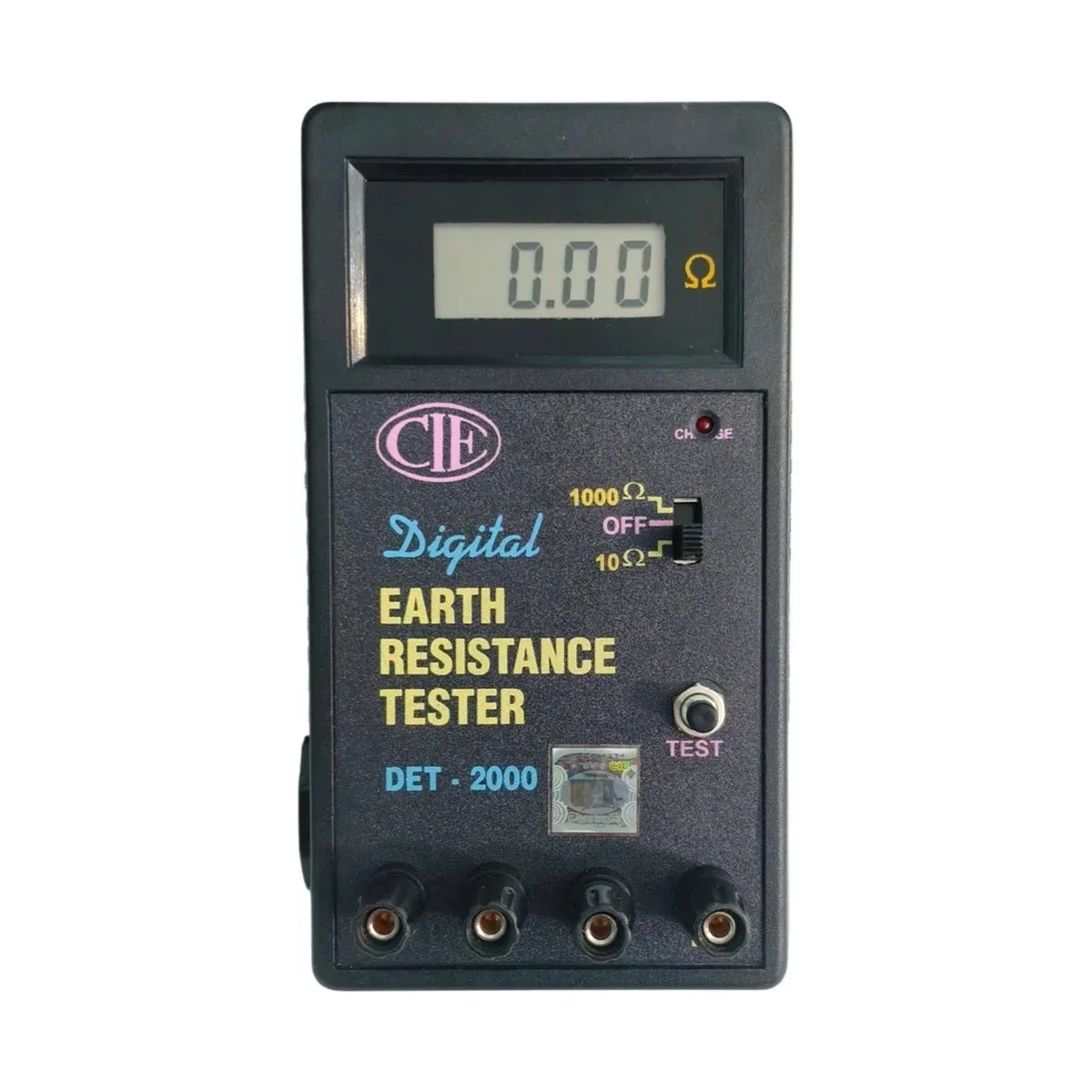
 DET-2000
Why do I need to disconnect the electrode?
Otherwise you measure the electrode in parallel with every other path to earth in the installation, and you cannot tell how good the electrode itself is. Disconnecting also keeps the test current out of live equipment.
How far apart should the spikes be?
As a starting point, 15 to 21 m for each step, in a straight line. Larger electrodes or poor soil may need greater spacing. The check of moving the middle spike tells you if the spacing is enough.
Why is my reading unstable?
Poor contact between spike and soil, nearby buried metal, or stray currents. Wet the soil around the spikes, move the line away from pipes and cables, and repeat.