The short answer
Isolate, prove dead, disconnect anything electronic, pick the test voltage from the equipment rating, hold the test for one minute (ten for PI), note the temperature, then discharge before you touch anything. Compare the reading to the minimum for your standard and to the last reading you took.
Before you start
- Isolate the equipment and lock it out. Prove it is dead with a voltage tester or multimeter.
- Disconnect it from the supply, the VFD or soft starter, surge arrestors, capacitors, electronic meters and any control wiring that could be damaged.
- Discharge the equipment to earth, particularly cables and large windings that can hold charge.
- Clean and dry the terminal area. Dirt and moisture on terminals give a false low reading.
- Check your tester and leads. Look for damaged insulation on the leads and a healthy battery. Briefly test the tester on a known good value if it has a test facility.
Choose the test voltage
| Equipment | Suggested test voltage | Common minimum |
|---|---|---|
| Control wiring, SELV and PELV circuits | 250 V | 0.5 MΩ |
| LV wiring and equipment up to 500 V | 500 V | 1 MΩ |
| 415 V motors, panels, busbars | 500 V or 1000 V | 1 MΩ |
| 3.3 kV motors and cables | 1000 V to 2500 V | Rated kV plus 1 MΩ |
| 6.6 kV and 11 kV equipment | 2500 V or 5000 V | Rated kV plus 1 MΩ |
Minimums follow IEC 60364-6 for installations and IEEE 43 for motors and generators. Follow your own site or manufacturer limits if they are stricter.
Testing a motor
- Open the terminal box and separate the star or delta links so each winding is independent, if the procedure allows.
- Connect the tester's EARTH lead to the motor frame (a bare, clean metal point) and the LINE lead to one winding terminal.
- Select the test voltage and press and hold the test button. Read the value at 60 seconds and note it.
- Repeat for each winding to earth. If you want to check winding to winding, test one against the others.
- For large or HT motors, run the test for 10 minutes and record the reading at 1 minute and 10 minutes for the PI.
- Release the test and let the tester discharge the winding. Short the terminals to earth for a few minutes before touching.
Testing a cable
- Disconnect both ends and keep the far end clear of any metalwork and people.
- For a multicore cable, test each core to earth (armour or screen) with the other cores also connected to earth, then test core to core.
- Apply the test voltage for one minute and record the reading. Longer cables have lower resistance because they have more insulation in parallel, so compare like with like.
- Discharge each core to earth before reconnecting. HT cable can hold charge for a long time.
Testing a panel or busbar
- Isolate the incomer and open all feeder switches so the busbars are clear.
- Disconnect electronics, meters and surge protection devices.
- Test each phase to earth and each phase to the others, at 500 V or 1000 V.
- A low reading often points to dust, damp or tracking on the insulators. Clean, dry and test again.
Reading the result
- Compare against the minimum for your standard. Anything below it should be investigated before the equipment is put back into service.
- Compare against the last reading. A steady downward trend over years is an early warning, even if the number is still above the minimum.
- Temperature matters. Insulation resistance roughly halves for each 10 °C rise, so correct readings to a reference temperature (40 °C is common) or record the temperature with each result.
- Use PI and DAR when you can. The PI is the 10 minute reading divided by the 1 minute reading; 2 or more is generally healthy. The DAR is the 60 second reading divided by the 30 second one; above about 1.4 is generally good.
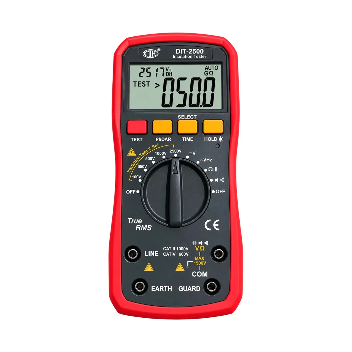
PI and DAR built in
 DIT-2500
Digital Insulation Tester + Multimeter - up to 2500 V
Selectable timer (15 s, 30 s, 1 min, 10 min) and automatic DAR and PI, so you do not have to time the test by hand.
₹8,500
₹12,740 33% off
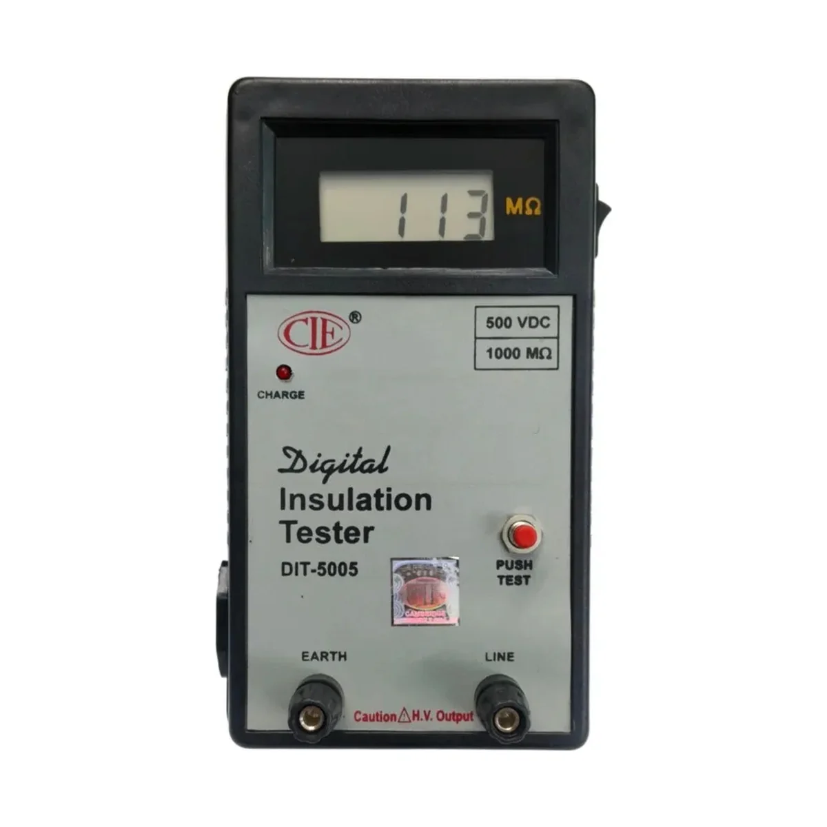
For routine LV testing
DIT-5005
Digital Insulation Tester
One-button testing at 500 V or 1000 V with a direct megohm reading. Hard-wearing and easy for any member of the team to use.
₹4,530
₹6,800 33% off
For HT equipment
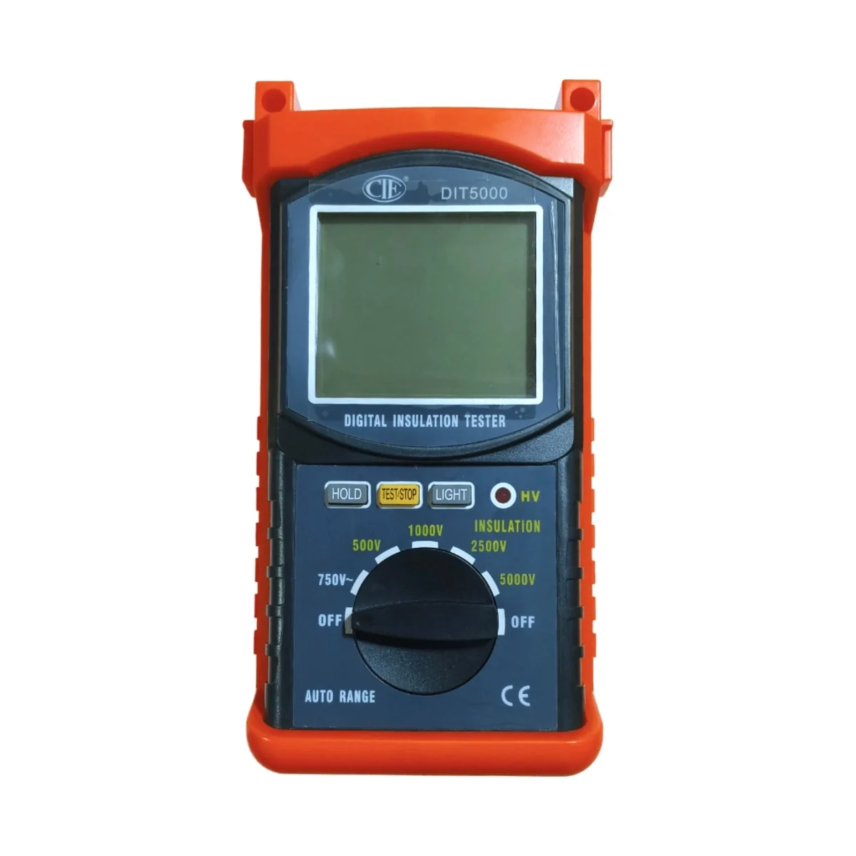
DIT-5000
Digital Insulation Tester - up to 5000 V / 200 GΩ
Tests at 5000 V with a live-output LED and auto-ranging up to 200 GΩ.
₹11,330
₹16,990 33% off
How long should I hold the test voltage?
One minute is the standard time for a spot reading. For a polarization index, hold it for ten minutes and record the reading at one minute and at ten minutes.
Why does my reading keep rising during the test?
That is normal. As the insulation polarises, the leakage current falls and the resistance climbs. A reading that rises well indicates healthy insulation. A reading that stays flat or falls suggests moisture or contamination.
Can I test a motor connected to a VFD?
No. Disconnect the motor from the drive first. The test voltage can damage the drive electronics.
What if the reading is below the minimum?
Do not energise the equipment. Dry it out, clean the terminals, and test again. If it stays low, the insulation needs repair or rewinding.